MAGNETIC EFFECTS OF ELECTRIC CURRENT NOTES
INTRODUCTION
The science of magnetism developed from the observation that a certain ore could attract bits of iron and point in a particular direction when freely suspended. This ore was originally found in the district of Magnesia in Asia Minor (Magnesia is the modern town of Manisa in Western Turkey) and was, therefore, named Magnetite.
The property of attracting small pieces of iron was referred to as magnetism.
A magnet is a substance that has both attractive and directive properties.
Later on, in 1600, Dr. William Gilbert confirmed that the Earth itself behaved as another natural magnet
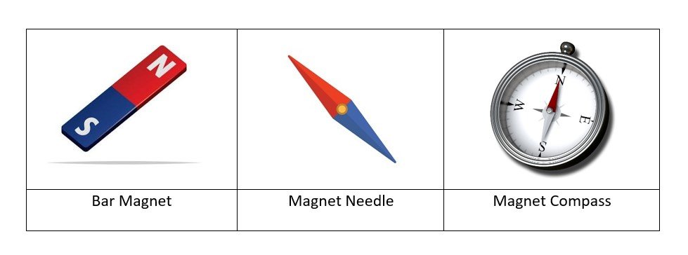
The natural magnets are weak and often irregular in shape. It is found that when natural magnets are rubbed against iron or steel bars, the same property of attraction is communicated to these bars. These are, therefore, called artificial magnets. Artificial magnets that can be of a desired shape and length. Different types of artificial magnets, which are most commonly used, are shown below.
Bar Magnet
- A bar magnet is a solid, typically rectangular object made of materials like iron, steel, etc., with natural magnetic properties.
Properties of Magnet
(i) Every magnet has two poles, i.e., North and South.
(ii) Like poles repel each other.
(iii) Unlike poles attract each other.
(iv) A freely suspended bar magnet aligns itself in nearly a north-south direction, with its north pole towards the north direction.
MAGNETIC FIELD AND MAGNETIC FIELD LINES
The space around a magnet in which the force of attraction and repulsion due to the magnet can be detected is called the magnetic field.
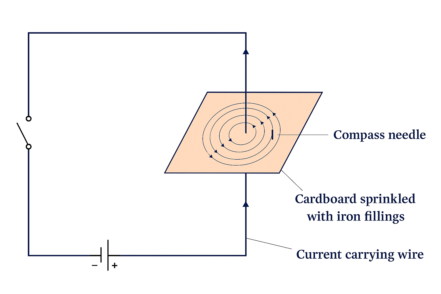
A convenient method to describe the magnetic field around a magnet is to draw magnetic field lines around it. To do so, place a magnet on a cardboard sheet and gently sprinkle some iron filings uniformly over it. The iron filings are found to arrange themselves in a pattern shown in Fig.
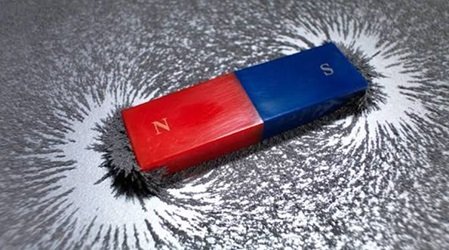
These curved paths along which the iron filings arrange themselves due to the force acting on them in the magnetic field of the bar magnet are called magnetic field lines.
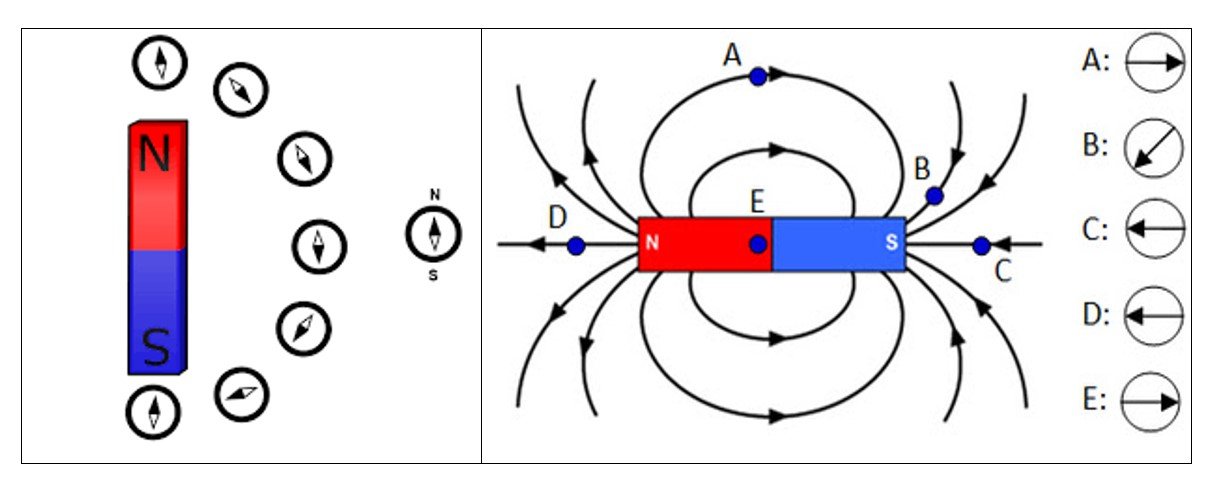
Tracing (or mapping) the Magnetic Field due to a Bar Magnet using a Compass
Properties of Magnetic Field Lines
- A magnetic field line is directed from the north pole to the south pole outside the magnet.
- A magnetic field line is a closed and continuous curve.
- The magnetic field lines are crowded near the pole, where the magnetic field is strong, and are far apart near the middle of the magnet and far from the magnet, where the magnetic field is weak.
- The magnetic field lines never intersect each other because if they do so, there would be two directions of the magnetic field at that point, which is absurd.
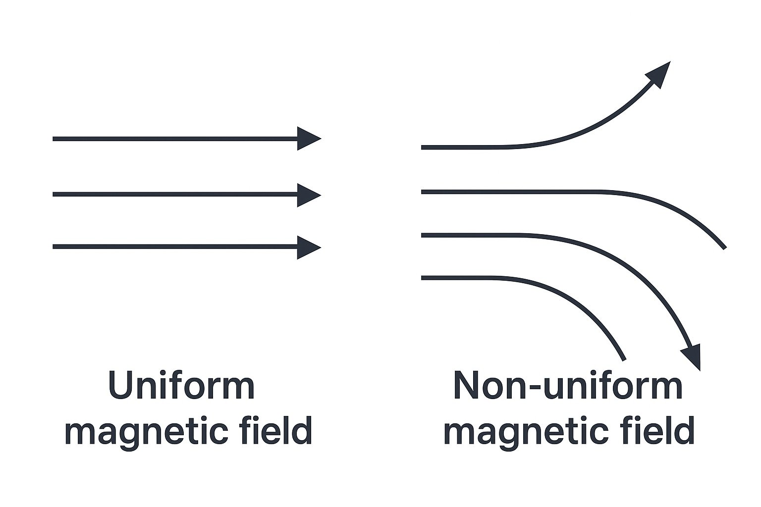
- In case the field lines are parallel and equidistant, these represent a uniform magnetic field. The Earth’s magnetic field is uniform in a limited Space.
OERSTED DISCOVERY- EXPERIMENTAL EVIDENCE OF THE RELATION BETWEEN ELECTRICITY AND MAGNETISM
Oersted experiment demonstrated that around every conductor carrying an electric current, there is a magnetic field. In other words, we can produce magnetism from an electric current.
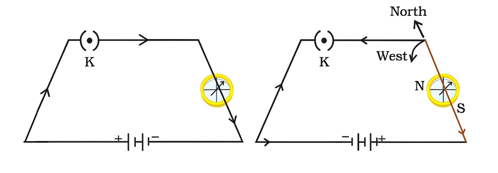
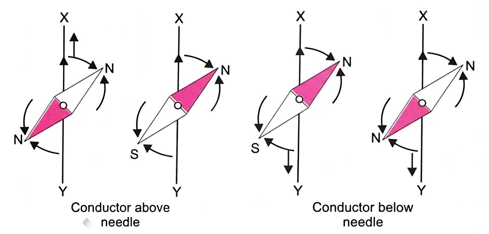
On reversing the direction of the current, the needle moved in the opposite direction. On further investigation, Oersted found that the direction of deflection of the needle depended not only on the direction of current but also on whether the conductor was above or below the needle.
Ampere’s Swimming Rule
Let the observer imagine himself to be swimming along the conductor in the direction of the current and facing the magnetic needle, then the north pole of the needle will be deflected towards his left hand.
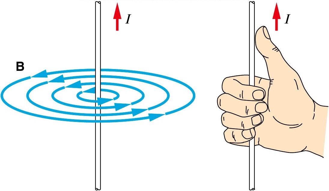
MAGNETIC FIELD DUE TO A CURRENT-CARRYING STRAIGHT CONDUCTOR
When a current is passed through a straight conductor(conducting wire), a magnetic field is produced around it. and it is in the form of concentric circular field lines with the conductor at the centre.
If the direction of the current is from X to Y, the direction of the field lines is clockwise.
If the direction of the current is reversed so that the current flows from X to Y, the direction of the field lines is also reversed, ie, these field lines are clockwise 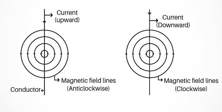
Direction of Magnetic Field: Right-Hand Thumb Rule
To find the direction of the magnetic field due to a straight current-carrying conductor, we use the Right-Hand Thumb Rule, which is as follows.
Imagine the straight conductor in your right hand such that the thumb points in the direction of the current. The direction of curling of the fingers of the right hand gives the direction of the magnetic field lines.
Magnitude (B) of Magnetic Field
1. If the current in conductor XY is increased, the compass needle deflection also increases. The magnitude of the magnetic field(B) increases if the current(I) is increased.
Magnetic field ∝ Strength of current
B∝ I
2. If the distance (r) of the compass from the conductor is increased, the deflection of the needle decreases. The magnitude of the magnetic field decreases if we move away from the wire.
Magnetic field ∝ Distance
B∝ 1/r
UNIT OF MAGNETIC FIELD
The unit of magnetic field is tesla(T) in honour of Nikola Tesla.
A smaller unit of magnetic field is called gauss (G), where 1T = 10⁴ G
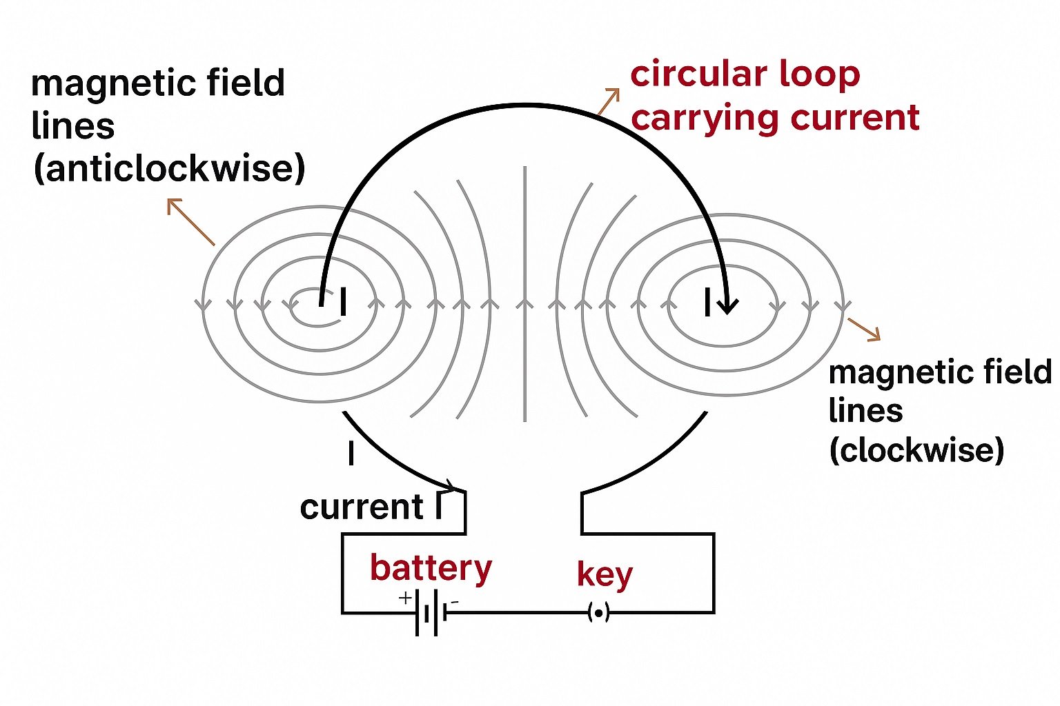
MAGNETIC FIELD DUE TO A CURRENT-CARRYING CIRCULAR COIL
1. The magnetic field lines near the coil are nearly circular and concentric.
2. Near the centre of the coil, the field lines are nearly straight and parallel. The magnetic field at the centre of the coil can be taken to be uniform.
3. The magnetic field is maximum at its centre.
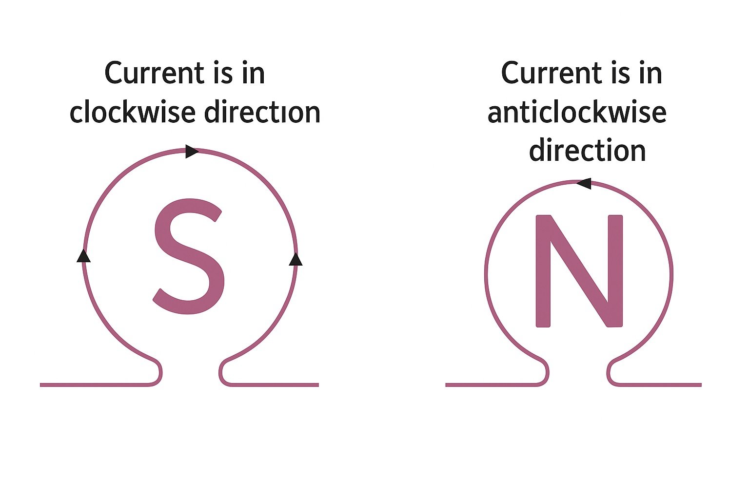
Direction of Magnetic Field: Clock Rule
Look at one face of the circular wire or coil through which current is passing.
- If the current flows in a clockwise direction, that face of the coil is a South Pole (S-pole).
- If the current flows in an anti-clockwise (or counter-clockwise) direction, that face of the coil is a North Pole (N-pole)
Magnitude (B) of Magnetic Field
The magnitude of the magnetic field (B) at the centre of the coil is :
1. directly proportional to the current (1) flowing through it, i.e.,
B∝ I
2. inversely proportional to the radius (r) of the coil, ie,
B∝ 1/r
3. directly proportional to the total number of turns (N) in the coil, ie,
B∝ N
Combining (1), (2), and (3), we obtain
B∝ NI/r
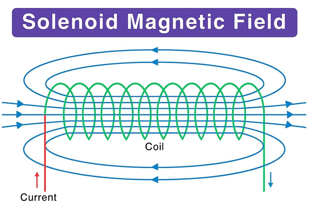
MAGNETIC FIELD DUE TO A CURRENT-CARRYING SOLENOID
An insulated copper wire wound on a cylindrical cardboard (or plastic) tube such that its length is greater than its diameter is called a solenoid.
- The magnetic field inside a solenoid is uniform.
- A current-carrying solenoid behaves like a bar magnet with fixed polarities at its ends.
Direction of Magnetic Field:
The Direction of the Magnetic Field can be determined by the clock rule
Magnitude (B) of Magnetic Field
The magnitude of the magnetic field (B) at the centre of the coil is :
1. directly proportional to the current (1) flowing through it, i.e.,
B∝ I
2. inversely proportional to the radius (r) of the coil, ie,
B∝ 1/r
3. directly proportional to the total number of turns (N) in the coil, ie,
B∝ N
ELECTROMAGNETS AND PERMANENT MAGNETS
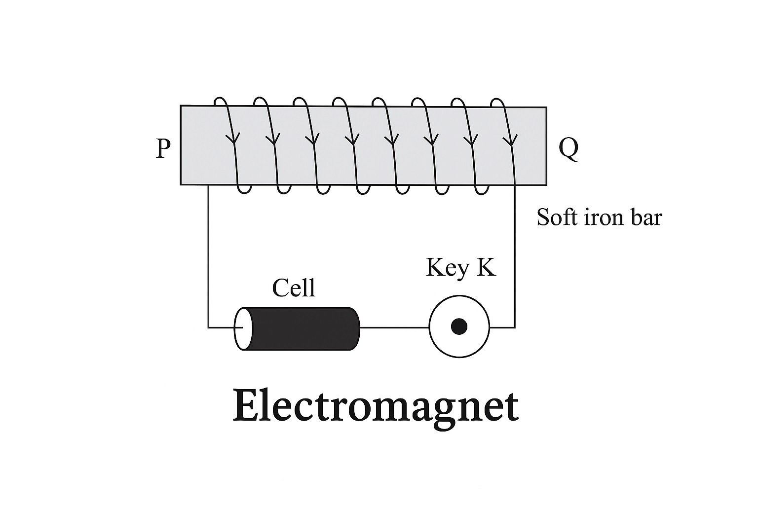
(a) Electromagnet. An electromagnet is a temporary strong magnet and is just a solenoid with its winding on a soft iron core.
The strength of the electromagnet depends upon :
(i) the number of turns per unit length of the solenoid and
(if) The current through the solenoid.
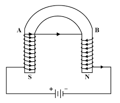
To provide a strong magnetic field in a small region, an electromagnet is made in a U-shape. Such a magnet is called a horseshoe magnet
Uses of Electromagnets
1. Electromagnets are used in electrical devices such as an electric bell, an electric fan, a telegraph, an
electric train, an electric motor, a generator, etc.
2. For lifting and transporting large masses of iron in the form of girders.
3. In medical practice for removing pieces of iron from wounds.
(b) Permanent Magnet. A permanent magnet is made from steel. As steel has more retentivity than
iron, it does not lose its magnetism easily.
Apart from different varieties of steel (carbon steel, chromium steel, cobalt and tungsten steel), some
alloys like Alnico (Aluminium; Nickel-Cobalt alloy of iron) and Nipermag (an alloy of iron, nickel,
aluminium and titanium) They are used to make very strong permanent magnets.
Uses of Permanent Magnets.
Permanent magnets are used in
(i) electric meters (galvanometers, voltmeters, ammeters, speedometers, etc.),
(i) microphones and loudspeakers and
(ifi) electric clocks.
| ELECTROMAGNET | PERMANENT MAGNET |
|---|---|
| 1. An electromagnet is a temporary magnet as it can readily be demagnetised by stopping the current through the solenoid. 2. An electromagnet produces a strong magnetic field whose strength can be changed by changing the current through the solenoid3. The polarity of a clectromagnet can easily be reversed by changing the direction of current through the solenoid. |
1. A permanent magnet cannot be readily demagnetised.
2. The magnetic field of a permanent magnet is comparatively weak, and its strength cannot be changed. 3. The polarity of a permanent magnet is fixed and cannot be easily reversed. |
FORCE ACTING ON A CURRENT-CARRYING CONDUCTOR IN A MAGNETIC FIELD
When a current-carrying conductor is placed in a magnetic field, it experiences a force, except it is placed parallel to the magnetic field.
The Kicking Wire Experiment has been designed to show the relation between the
direction of force acting on a wire (i.e., a conductor) carrying current
- When the key X is closed, the current flows downwards and the hanging wire swings forward with mercury and breaks the circuit. When the (shown by a dotted line). This causes the wire to leave contact wire falls back to its original position, it remakes contact with mercury, and the action is repeated.
2. On reversing the battery connections, the current in the wire flows upwards and it swings backwards out of mercury.
Magnitude of Force
(i) directly proportional to the current (I) flowing through the conductor, ie,
F∝ I
(i) directly proportional to the length (L) of the conductor inside the magnetic field, i.e.,
F∝ L
(iii) directly proportional to the magnitude (B) of the magnetic field, i.e.,
F∝ B
Combining (1), (2) and (3), we get
F∝ ILB
or
F=kILB
where k is a constant of proportionality.
In SI units, k = 1. Thus, F=ILB
In case, I = 1 ampere, L = 1 metre, and F = 1 newton, B = 1 tesla. Thus,
The magnitude of the magnetic field is 1 tesla (T) if a conductor of length 1 metre (m) carrying a current of 1 ampere (A) experiences a force of 1 newton (N) when placed perpendicular to the direction of the magnetic field.
Fleming Left-Hand Rule (Motor Rule)
Stretch the thumb, the first finger, and the central finger of the left hand so that they are
mutually perpendicular to each other. If the first (fore) finger points in the direction of the magnetic field, the central finger points in the direction of current, then the thumb points in the direction of force on the conductor.
FORCE ACTING ON A CHARGE MOVING IN A MAGNETIC FIELD
A charge moving in a magnetic field experiences a force, except when it is moving in a direction parallel to it.
Magnitude of Force
Force (F) acting on a conductor of length, L, and carrying a current, I, when placed in a direction
perpendicular to the direction of the magnetic field of magnitude B is given by
F=ILB
Since current is the rate of flow of charge,
I=q/t
F=q/t.LB
As L/t = v (velocity of the charged particle)
F=qvB
Direction of Force: Fleming’s left-hand rule.
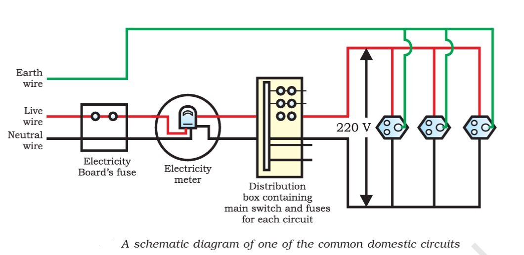
DOMESTIC ELECTRIC CIRCUITS
In our homes, we receive supply of electric power through a main supply (also called mains), either supported through overhead electric poles or by underground cables. One of the wires in this supply, usually with red insulation cover, is called the live wire (or positive). Another wire, with black insulation, is called the neutral wire (or negative). In our country, the potential difference between the two is 220 V. At the meter board in the house, these wires pass into an electricity meter through a main fuse. Through the main switch, they are connected to the line wires in the house. These wires supply electricity to separate circuits within the house. Often, two separate circuits are used, one of 15 A current rating for appliances with higher power ratings, such as geysers, air coolers, etc. The other circuit is of 5 A current rating for bulbs, fans, etc. The earth wire, which has insulation of green color, is usually connected to a metal plate deep in the earth near the house. This is used as a safety measure, especially for those appliances that have a metallic body.
EARTHING
This is used as a safety measure, especially for those appliances that have a metallic body, for example, an electric press, toaster, table fan, refrigerator, etc. To avoid serious accidents such as short-circuit, the metal casing of the electric appliance is earthed. Since the earth does not offer any resistance, the current flows to the earth through the earth wire instead of flowing through the body of the person.
SHORT-CIRCUITING
In general, short-circuiting occurs when the ends of a circuit are connected by a conductor of very
low resistance compared to that of the circuit. In household connections, short-circuiting occurs when the live (positive) wire and the neutral (negative) wire come in direct contact with each other. This happens due to
(i) damage to the insulation of the power lines
(ii) a fault in an electrical appliance, due to which current does not pass through it.
ELECTRIC FUSE: A SAFETY DEVICE
To avoid incidents like electric shock, fire, or damage to an electric appliance due to (i) short-circuiting
or (ii) overloading (withdrawing current beyond a specified limit) in a circuit.
An electric fuse is a device which is used in Series to limit the current in an electric circuit so that it easily melts due to overheating when excessive current passes through it. A fuse is a | wire of a material with very low melting point.
A fuse wire is made of a wire of an alloy of lead (75%) and tin (25%).
1. A fuse is always connected in the live wire and not in the neutral wire under any circumstances.
2. A fuse is always connected in the beginning of the circuit before any appliance is connected.
3. The thicker the fuse wire, the greater its current capacity.
4. A fuse used must be of current capacity (also called current rating) less than the maximum current that a circuit or appliance can withstand.